


Definition of Wave overtopping:
Wave overtopping refers to the average quantity of water that is discharged per linear meter by waves over a protection structure (e.g. breakwater, dike) whose crest is higher than the still water level (SWL).
This is the common definition for Wave overtopping, other definitions can be discussed in the article
Notes
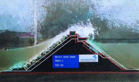
Pictures of wave overtopping in the laboratory and in the field are shown in Fig. 1; a schematic representation with definitions is displayed in Fig. 2. During overtopping, two important processes take place: wave run-up on the structure and partial transmission of waves. The process of wave overtopping is highly random in time, space and volume; there is no permanent discharge over the crest of a structure. The highest waves may wash a large volume of water over the crest in a short period of time (less than a wave period), whereas lower waves may not produce any overtopping.
An empirical formula for the average water discharge q per linear meter by waves over a protection structure is given in the EurOtop manual[1]
qgH3m0−−−−−√≡q∗=0.09exp(−1.5RcγfHm0),(1)
for perpendicular wave incidence. Since observational overtopping rates of more than a factor 10 higher were observed in several experiments, a revised formula was developed by Eldrup et al. (2022[2]). The general form of the wave overtopping discharge is
q∗=aexp[(−bRcHm0)c],(2)
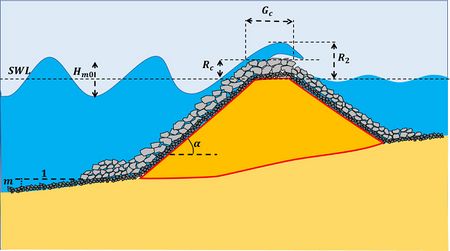
Fig. 2. Waves overtopping a breakwater; definition of symbols.
where the coefficients a,b,c depend on (see Fig. 2):
- The spectral wave height at the toe of the structure Hm0 (approximately equal to the significant wave height Hs, see Statistical description of wave parameters)
- The spectral wave energy period Tm−1,0
- The water depth htoe at the toe of the structure
- The breakwater wave run-up R2 exceeded by only 2 % of the waves; R2/Hm0 depends on the roughness (and permeability) reduction factor γf, the surf similarity parameter ξ and the wave obliqueness,
- The freeboard Rc (the structure crest level relative to the still water level (SWL);
- The seabed slope m
- The front slope of the structure tanα
- The crest width of the structure Gc
- The surf similarity parameter (Iribarren number) ξ=Tm−1,0tanαg2πHm0−−−−−−√
- The roughness (and permeability) reduction factor γf that accounts for the roughness and percolation of structures’ slope. The reduction factor γf may further depend on the surf similarity parameter and the overtopping flow rate. Usual values for rubble mound structures are in the range γf∼0.4–0.6.
Typical design values are in the range: Hm0∼2-5 m, Tm−1,0∼8-15 s, htoe/Hm0∼1-4, R2/Hm0∼2-6, Rc/Hm0∼1-3, Gc/Hm0∼1-3, tanα∼0.25-0.6, m∼0.005-0.05, ξ∼2-8.
A simpler formula for overtopping of rubble mound breakwaters by surging waves was empirically derived by Etemad-Shahidi et al. (2022[3]):
q∗=(1.22±0.13)10−4exp[(3.5±0.13)R2−RcHm0–(0.64±0.07)GcHm0].(3)
The standard deviation of observational data with respect to this formula is about a factor 3. This uncertainty is mainly related to estimating the wave run-up. The EurOtop manual[1] proposes for approximately normal wave incidence:
R2=1.65γfHm0ξ, with a maximum of γsfHm0(4−1.5ξ−1/2). The friction factor γsf for surging waves is estimated as γsf=γf+0.12(1−γf)(ξ−1.8) with a minimum value equal to γf.
The formulas (1,3) overpredict the wave overtopping for very shallow foreshores where htoe/Hm0<0.5 [4].
